[From Bruce Abbott (2018.09.09.1715 EDT)]
The youtube video at https://youtu.be/4Y7zG48uHRo uses the example of an auto-steering car to illustrate the operation of a PID (proportional-integral-derivative) controller. The video presented the basic output function of the controller, which can be written as
Output = kpproportional error + kdderivative error + ki* integral error, where kp, kd, and ki are the respective gains for each error term.
The video illustrated how each of these terms contributes to the performance of the car as it attempts to travel down the center of its lane. The simulation begins with the car offset from lane center. To correct positional errors, the system varies the steering angle of the front wheels, which changes the car’s direction of travel, or heading. The car’s forward speed then carries the car in the direction of the heading.
With proportional control alone, the position error causes the steering angle to change in proportion to the error and in the direction of the reference position (lane center). As the car approaches the reference position, the error decreases, reducing the steering angle, until the steering angle becomes zero (straight ahead) as the car crosses lane center. Unfortunately the heading is at that point still at an angle relative to the lane and the car therefore passes center. As error develops on the other side, the steering angle changes to move the car back toward center and the whole scenario repeats. The result is a car that weaves continually back and forth across the centerline.
The addition of the derivative term makes the system sensitive to the rate at which the car’s position relative to the reference (the error) is changing. The rate of change in error (multiplied by a suitable gain) is added to the proportional term. In effect this allows the system to “anticipate” what the error value will be in the next iteration of the control loop and adjust the steering angle accordingly. Because the error is decreasing as the car approaches lane center, the steering angle is reduced relative to the purely proportional system, allowing the car to approach the centerline at a heading more nearly aligned with the lane.
In the video simulation, the car hits some rocks, bending its steering out of alignment. The car is knocked out of position but quickly recovers; however, it does not return to lane center. Instead, it runs parallel to the lane but at an offset relative to the reference position. The reason for this offset is that an error of zero no longer keeps the steering angle at zero due to the steering misalignment. To compensate so that the car goes straight, the controller must set the wheel angle at a value opposite to the misalignment, so that the net steering angle is again zero when the car is moving straight down the lane. But steering angle is proportional to error, and the only way to generate a compensating wheel angle is to allow a sufficient offset (error) to develop.
The integral term was added to correct this offset. The integral term sums the error across iterations of the loop. As the error builds, the steering angle changes to bring the car toward the centerline, and as the car approaches the centerline, the rate of error increase diminishes. When the car reaches the centerline, the cumulated error will be exactly that which is required to keep the net steering angle at zero. The car will track down the centerline but with a steady error just large enough to produce a net steering angle of zero despite the misalignment.
The video does not provide the formulas by which steering angle and the car’s forward motion change the car’s heading, nor for how the heading changes the car’s position – or in other words, the environmental linkages through which the control system must act. Nevertheless it’s not difficult to figure out. My particular implementation simulates the mechanics but ignores the physics involved in accelerating masses or determining tire adhesion to the road. I could add these, but unless the car is assumed to be traveling at high speed (so that centripetal forces are large) or on a slippery surface (causing the car to skid) I don’t believe these additions would change much. It is unclear whether the physics is modeled in the youtube simulation, although I would guess not.
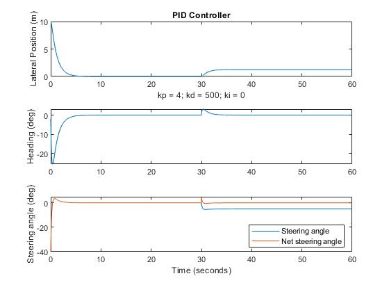
The following figures depict the performance of the PID controller. First, I present the PID controller simulation with only the proportional and derivative terms at work (the integral gain was set to zero). Second, I present the same with the integral term added (integral gain > zero). Note that the gain values selected probably are not optimal ones; I simply adjusted them until control seemed to work reasonably well.
PID Controller Simulation: Proportional + Derivative only
The top panel shows the car’s later position relative to lane center (reference position) as a function of time, for 60 seconds. Immediately below this panel are the proportional, derivative, and integral gains used in the simulation. The middle panel depicts the car’s heading relative to the lane, with zero being parallel to the road. The bottom panel shows the steering angle. At 30 seconds, the car hits those rocks, knocking the steering out of alignment by 5 degrees. As the top panel shows, following recovery from the “rocks” disturbance, the car maintains a position parallel to the lane but offset from it. The bottom panel shows both the nominal steering angle (in which zero position error would produce “straight head” driving before the misalignment) and the net steering angle produced by the misalignment plus any counteracting wheel turn. After the encounter with the rocks, the car changes its nominal steering angle so that the net angle is zero once the system re-stabilizes.
PID Controller Simulation: Proportional + Derivative + Integral
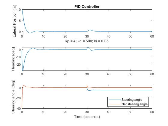
In this simulation run, the integral gain is > zero so the integral term now has an effect on performance. You can see some effect of this addition prior to the disturbance in that there is a bit of overshoot and undershoot following the initial approach to lane canter. But after the steering misalignment, the offset that was clearly evident in the PD version quickly disappears, although the steering angle is again adjusted to compensate for the misalignment.
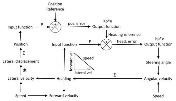
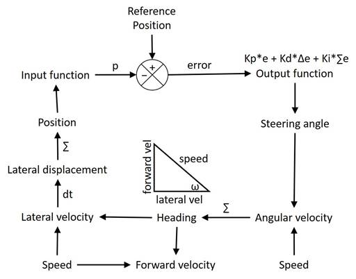
For those who might be interested, here is a system diagram:
The triangle depicted at center shows how the car’s speed translates to forward and lateral velocity relative to the lane, based on the heading angle, ω. The output function determines the steering angle. The car’s steering angle and speed determine its angular velocity – how rapidly its heading changes. Integrating the angular velocity yields the current heading, which in turn determines both the forward and lateral velocities. Taking the derivative of lateral velocity gives the change in lateral displacement during loop iteration, and summing these changes gives the current lateral position. The difference between the sensed position and the reference position determines the position error.
The PCT Controller
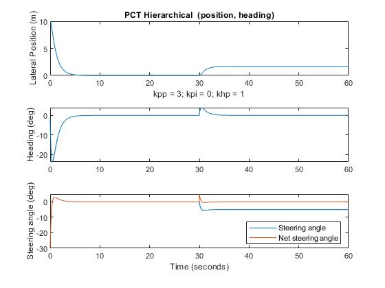
To provide a contrast to the PID controller, I created a two-level hierarchical controller. The top level controls the car’s position by varying the reference for the bottom level, which controls the car’s heading. Both control systems employ proportional control in their output functions; the position controller adds an integral term. The mechanical linkages in the environment are unchanged from the PID version. Here are the simulation results:
The PCT Controller: Proportional control only
The terms kpp, and kpi represent the proportional and integral gains of the position control system; the khp term is the proportional gain of the heading control system.
If you compare the performances of this system and that of the PD controller, you will see that they are almost identical. (The difference may be due to the gain values selected for each.) As with the PD controller, the system maintains an offset from lane center after the encounter with the rocks, and stays parallel to the road by adjusting the steering angle to compensate for the steering misalignment.
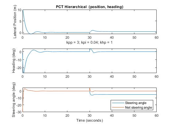
The PCT Controller: Proportional + Integral (position); Proportional (heading)
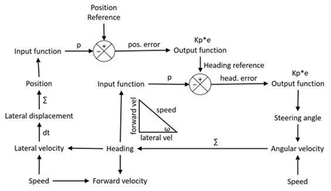
The performance closely resembles that of the PID controller. Here is the system diagram:
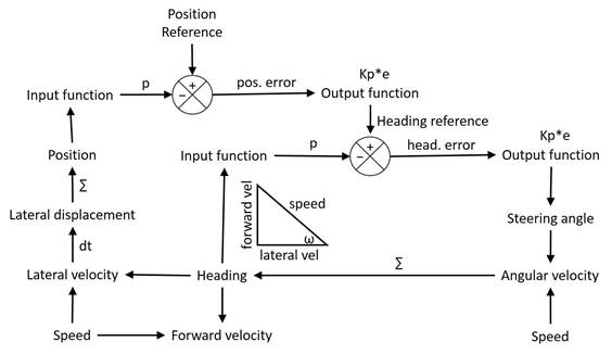
Here, the output of the position control system sets the reference for the heading control system. Because of this, the heading becomes more nearly parallel to the lane the closer the car gets to lane center, accomplishing in a more natural way what derivative control does for the PID controller. The output of the heading controller varies the steering angle to control both the heading and, through the effects of heading and speed on lateral position, the position of the car relative to lane center.
Discussion
Both controllers do a reasonably good job of controlling the car’s position relative to the reference. In the absence of an integral term in the output function of the position control system, both produce a position offset from reference after the steering misalignment, and with both, the addition of the integral term allows the car to return the its reference position despite the misalignment, by changing the steering angle to compensate for the misalignment.
The hierarchical control system seems easier to tune and may be capable of better performance than the PID controller when both are optimally adjusted. The hierarchical system is stable using only proportional control; in contrast the PID system required a derivative term to eliminate oscillations (by phase advance). Both are control systems in the canonical PCT style. I see no evidence that engineers view the PID system as controlling output, where output is defined as the actions (means of control) of the system. Both systems are designed to control the position of the car relative to a reference position and both do so by means of error between perceptions and corresponding reference values. However, for engineers the term “output” refers to the variable being controlled and “input” to the reference value. Given that these terms are used differently in PCT this likely to cause confusion among PCTers about what engineers are referring to when they use these terms.
Bruce
