[From Bill Powers (2009.12.25.1830 MDT)]
Bruce Abbott (2009.12.25. 1615 EST) –
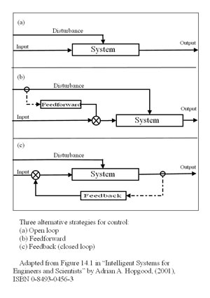
BA: Heres a set of diagrams that appear on Wikipedia distinguishing
between pure open loop (feednowhere), feedforward, and feedback
systems, as defined in engineering:

Note that, in these systems, the input is what we in PCT would call the
reference signal and the output is what we would call the input.
In the top (open loop) diagram, the input might be the setting on a
rheostat, which controls the speed of a motor. (Motor speed is the
output). A disturbance such as a load on the motor will cause the motor
speed to change from its speed setting and this open loop system will do
nothing about that. The motor will just slow to a new equilibrium
determined by the power setting and the load.
In the middle (feedforward) system, there is an added component that
senses the disturbance and passes its value to a comparator (the circle
with the x in it), where it is subtracted (after suitable scaling) from
the input. (Remember, the input is equivalent to PCTs reference.) The
system is still open loop (there is no feedback). Feedforward is scaled
so as to take account of the known effect of the disturbance on the
output; if done correctly, the changing input (reference) will be exactly
sufficient to offset the effect of the disturbance. For example, one
might work out exactly by how much the motor slows under various loads;
the feedforward system would measure the load and change the rheostat
setting so as to boost the power exactly the right amount to compensate
for the load.
BP: This is a qualitative argument, as well as being circular. Of course
if you do the scaling “correctly” for offsetting the effect of
the disturbance, the effect of the changing reference “will be
exactly sufficient to offset the effect of the disturbance.” That is
what “correctly” means. But if you do it incorrectly, which is
almost inevitable when you try to accomplish this with a real system, the
sufficiency comes into doubt.
Adding to the input a signal indicating the size and direction of a
disturbance is not enough to counteract the effect of the disturbance on
the output. As in Cooper’s diagram, you need a computer in the link to
calculate the size of the effect of the disturbance on the output via the
system that is disturbed. You need to take into account the intervening
properties of the System, the system’s effect on the motor, and the
motor’s response given the current load. It is highly unlikely that in
any real system these computations can be reduced to a simple adjustment
of a constant of proportionality.
In a true feedback control system, the nonlinearity of the intervening
System, and disturbances both anticipated and unanticipated, do not have
to be known in advance. If the controller is stable, all that matters is
the loop gain and the accuracy of sensing the controlled output. The
output (CV) will have the magnitude set by the input (reference signal)
as accurately as the output can be sensed.
This system would be most
beneficial if you were dealing with a sluggish system and the disturbance
could be sensed enough in advance of its effect on the output to overcome
the sluggishness. (The effect of the disturbance on the output would also
have to be stable over time.) That is, the system would begin responding
to the disturbance before it arrived, giving time for the slow response
to build up so that it takes effect in time to prevent much change in the
output.
How would you adjust this system to have just the right effect? You would
have to operate it and see what the result was. If the result wasn’t
right, you would make an adjustment of gain, linearity, and lag to make
the result closer to the desired one. As you continued to use this
system, you would have to continue monitoring its performance, comparing
the performance with what was desired, and making further adjustments.
But it wouldn’t matter if the performance kept changing unpredictably
with time and rough usage; you could keep the performance close to the
desired level because this system would just be part of the feedback
function between your adjustments and the sensed performance. The
accuracy of control of performance would be determined by the accuracy of
sensing, not the accuracy of the processes connecting input to
output.
Im old enough to remember the
Granatelli Indy turbine car that almost won the Indy 500 in 1967. The gas
turbine engine, which had been designed for use in helicopters,
responded sluggishly to throttle changes. Parnelli Jones, the driver of
the car, stated that he had to learn to get off the accelerator well
ahead of each turn and then mash it down as he entered the turn
something you definitely dont want to do when driving a
piston-engine car!
Right. Parnelli Jones was the negative feedback control system I am
talking about. He adjusted the way he produced output (timing and amount)
until the sluggish response was happening the way he wanted it to happen.
This required changing the relationship between the time of changing the
throttle setting and the desired time for the response to occur, and of
course between the amount of change of throttle setting and the amount of
response. This was not a set-it-and-forget-it adjustment; it went on
continuously, being affected, I would expect, by the changing weight of
the car, the condition of the tires, and the condition of the track
surface. The adjustment was done by negative feedback control of the
perceived result.
But the turbines lag was
so great that it would only begin to accelerate again as the car came
out of the turn. Jones was not actually behaving strictly as a
feedforward system (as defined in the second diagram), but one can see in
this example the benefit of advancing the changes in the reference signal
when the system changes its output only after a considerable delay.
Although not feedforward according to this strict engineering
definition, its easy to see how the term might actually be applied more
generally, to any system that uses prediction as part of its basis of
action.
And incorrectly, as I see it. I have given my reasoning in previous posts
today. What’s wrong with it?
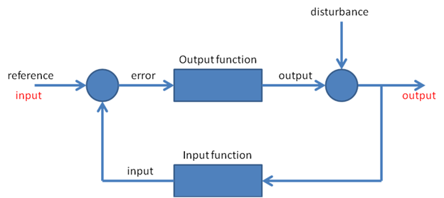
The bottom diagram shows the
usual negative feedback control system. The feedback is provided by a
sensor that determines the current state of the controlled variable (the
output) and subtracts this from the input. The resulting error signal
causes actions that oppose the effect of the disturbance. A feedback
regulated motor controller would have a sensor for motor speed. The
input speed setting would be compared to the actual motor speed as given
by the sensor and the difference between them would be used to generate
changes in motor torque as needed to compensate for changes in the
load.
If you used a two-level controller as in chapter 5 of LCS3, you would
find that the changes in throttle setting would increase by a large
amount when the reference-speed was changed, far more than needed for the
actual speed change. This would greatly reduce the apparent lag in
response of the engine, and it would be safe because the lower-order rate
control would quickly reduce the setting as the speed approached the new
reference setting. A driver might be able to learn to do this, though an
automatic controller could probably react faster.
The main thing being overlooked here is that negative feedback control is
based on long-term perceptions as well as short-term ones. When a driver
pulls into the pit area for a steering adjustment, it’s not because he
noticed a little pull or understeer on the previous turn. It’s because he
has been noticing this effect on enough turns to be sure it’s happening.
The adjustment is made not all at once, but in steps, because
overadjusting is as bad as underadjusting. It’s a control process
happening over many repetitions of some behavior, not just one.
It’s time, as Gary Cziko put it, to “put a model where one’s mouth
is.”
Best,
Bill P.

 there
there