Your last post in the topic “You say you want a revolution” under Learning PCT > Interdisciplinary Opportunities really belongs here. I’m including it by reference (using that link), but it really should be moved here.
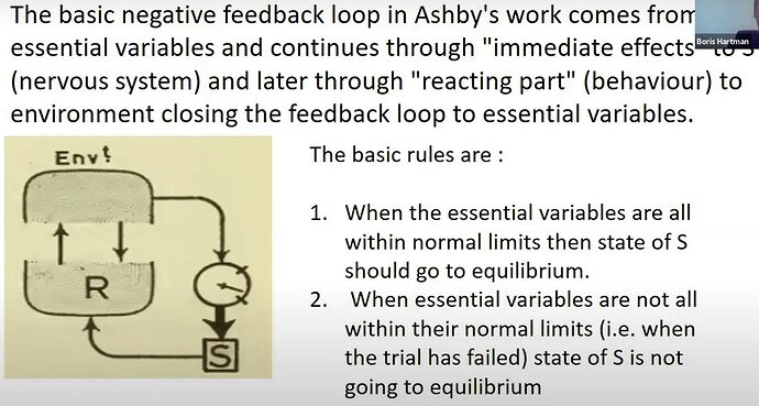
You start with Ashby’s feedback loop:
The little ‘dial’ figure seems to correspond to the comparator that is posited for the reorganizing system. This describes a loop that is closed through the environment. The “reacting part” R represents the entire control hierarchy of PCT (exclusive of the reorganizing system) which also constructs negative feedback loops which are closed through the environment. Those PCT feedback loops are represented by the two arrows between the gray blob labeled R and the other gray blob with Envt. written above it. So diagrammatically, it puts the entire PCT control hierarchy in a single black box in the environmental feedback path for the loop that Ashby is talking about.
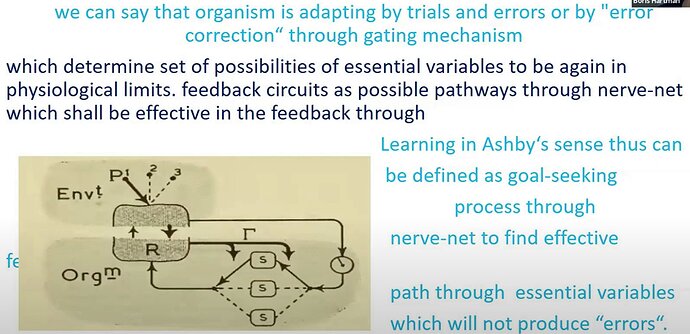
Your next diagram from Ashby is more complete. It shows a learning process within the organism, where one path from the dial-comparator through a ‘nerve-net’ is determined to be most ‘effective’ in reducing intrinsic error. The diagram suggests that the output of this path through the ‘nerve-net’ specifies what the control hierarchy R is to control. In PCT terms, a reference value of a certain strength is sent to the reference input function of a comparator in the hierarchy, and hierarchical control specifies further references signals cascading down to effectors influencing sensed environmental conditions. Ashby’s labels P and 1, 2, 3 are unexplained in this slide. Presumably they are environmental conditions which, being sensed, result in input of a perception of P1 to the dial-comparator, closing the loop that Ashby is concerned with.
There are now three boxes labeled S instead of one S. Do they represent different essential variables? Oxygen, potassium, and core body temperature, say? Seems more likely they would be variables like hormones and neurochemicals which can affect the essential variables, often rather indirectly.
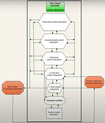
Now comes your “DBCS basic diagram”. There are many arrows, none of them labeled. Please help us to understand it. I find it quite confusing, and what I can make out in your talk has not cleared it up.
There’s a box with “Motor output” on the left and “sensory input” on the right. An arrow outside the box from Motor output to Sensory input closes the loop through the environment. There is one arrow out to Motor output, but there are two arrows in from Sensory input.
Beginning at the level of Motor output, you show five ascending levels of “control subsystems”. I assume these correspond to the first five levels of the proposed PCT hierarchy. Between each pair of levels are two arrows; the ascending arrow is presumably perceptual input to the one above, and the descending arrow is reference input to the one below.
Level 1 at the bottom sends output to “Motor output” on the left, so it seems to correspond to control of intensity signals from effectors. However, there is a descending line on the left, within the box, that seems to provide input to that arrow going to Motor output, and each of the other levels seems to provide output to that line and thence directly to motor output. This seems to say that each of these five levels provides input directly to “Motor output”. That is quite different from hierarchical control.
On the right, there appears to be sensory input to each of the first two levels. Which sensors directly produce sensations which are not constructed from intensities?
Level 5 has an additional output arrow on the left which provides input on the left to each of the levels below, except for Level 1; and Level 2 (I mistakenly wrote Level 1 at first) has an output on the right which provides input to each of the levels above, on an ascending line to which Level 3 and Level 4 also provide inputs.
Please label and explain each of these arrows.
So far this all appears to be a block diagram of R in Ashby’s diagrams above, what he called the ‘Reacting part’ of the organism.
Below level 1, a box labeled Essential variables and a box labeled Genetic control system has central input and output arrows going up and down connecting them to each other and to Level 1. In addition, Levels 2 and 3 have direct inputs to ‘Essential variables’, and ‘Essential variables’ has an output arrow up to Level 2.
Since this is the “basic diagram” I think we need to understand it before going on to your more elaborate diagram. Help us out.


