Robot Arm - adjustment and calibration

[From Adam Matic 1.4.2012.21.30 CET]

Greetings :slight_smile:

I need some help with fine-tuning parameters of a robotic arm.

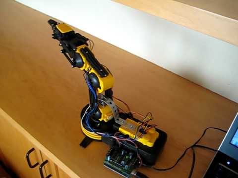
I used Vellman KSR10 (a.k.a OWI-535-Edge) robot arm kit and an Arduino to connect it to a computer. Since it’s a pretty basic robot arm, it doesn’t have servos, but simple DC motors. I have a few pots to measure joint angles and do some very crude speed measurements. I used the Little Man and LCS3 arm models as template programs.

First level loops just barely work (motor speed control) and I hope they can be improved without replacing DC motors with servos.

Second level loops (reach, elevation and lateral displacement control) also work, they get the job done, but overall behavior is not at all smooth.

I attached a video of the arm increasing reach while maintaining elevation. If it didn’t get trough, try http://www.2shared.com/video/NtSFb7nW/Robot_Arm.html

As you can see, there is room for improvement.

Some basic info:

The arm has 4 DoF. Loop interval is 50 ms (probably could be a bit better with optimisation).

Code is written in C# and Arduino C (Arduino is an Atmel328 based board connecting the computer with sensors and motors).

This is the first level loop code:

double ro;

double s = CurrentPot - LastPot;

VelocityBuffer[BufferCounter++] = s;

LastPot = CurrentPot;

if (BufferCounter == BufferSize) BufferCounter = 0;

Qi = AverageSpeed();

p = Qi * Ki;

ro = (Math.SignĀ® * (47 + Math.AbsĀ®));

e = ro - p;

Qo = Qo + (e - 0.5*Qo)*dt;

if (r == 0) Qo = 0;

if (Qo > 100) Qo = 100;

if (Qo < -100) Qo = -100;

speed = (int)(Qo);

////

Qi is a ā€˜moving average’ of last 10 readings.

The problem I had with getting the speed control to work is the minimum speed of the motor. It doesn’t go below 47 [pot values per 50 ms]. The speed range is basically 47 to 65 (no load). I use PWM to control the speed. So, any time reference signal is greater than zero, it becomes increased by 47. I tried reducing pot readings by 47 but that doesn’t work.

The ā€œif (r == 0) Qo = 0ā€ line is probably not very pretty. :smiley:

This is the main part of second level code:

Motor[0].r = (int)(LateralError);

Motor[1].r = (int)(-ElevationError - ReachError / 2);

Motor[2].r = (int)-ReachError;

Motor[3].r = (int)-ReachError;

///

I’ve tried everything I could think of to stabilise movement, this is the best I managed to do so far. I would appreciate any help.

Best

Adam

Robot Arm.3gp (2.68 MB)
Any sufficiently advanced technology is indistinguishable from magic.

Arthur C Clarke.

But some technologies are indistinguishable from April Fool jokes. To the uninitiated, of course.

Science is the process of eliminating supernatural explanations. - Robert Park

Ā·Ā·Ā·

From: Control Systems Group Network (CSGnet) [mailto:CSGNET@LISTSERV.ILLINOIS.EDU] On Behalf Of Adam Matic
Sent: Sunday, April 01, 2012 1:37 PM
To: CSGNET@LISTSERV.ILLINOIS.EDU
Subject: Robot Arm - adjustment and calibration

[From Adam Matic 1.4.2012.21.30 CET]

Greetings :slight_smile:

I need some help with fine-tuning parameters of a robotic arm.

I used Vellman KSR10 (a.k.a OWI-535-Edge) robot arm kit and an Arduino to connect it to a computer. Since it’s a pretty basic robot arm, it doesn’t have servos, but simple DC motors. I have a few pots to measure joint angles and do some very crude speed measurements. I used the Little Man and LCS3 arm models as template programs.

First level loops just barely work (motor speed control) and I hope they can be improved without replacing DC motors with servos.

Second level loops (reach, elevation and lateral displacement control) also work, they get the job done, but overall behavior is not at all smooth.

I attached a video of the arm increasing reach while maintaining elevation. If it didn’t get trough, try http://www.2shared.com/video/NtSFb7nW/Robot_Arm.html

As you can see, there is room for improvement.

Some basic info:

The arm has 4 DoF. Loop interval is 50 ms (probably could be a bit better with optimisation).

Code is written in C# and Arduino C (Arduino is an Atmel328 based board connecting the computer with sensors and motors).

This is the first level loop code:

double ro;

double s = CurrentPot - LastPot;

VelocityBuffer[BufferCounter++] = s;

LastPot = CurrentPot;

if (BufferCounter == BufferSize) BufferCounter = 0;

Qi = AverageSpeed();

p = Qi * Ki;

ro = (Math.SignĀ® * (47 + Math.AbsĀ®));

e = ro - p;

Qo = Qo + (e - 0.5*Qo)*dt;

if (r == 0) Qo = 0;

if (Qo > 100) Qo = 100;

if (Qo < -100) Qo = -100;

speed = (int)(Qo);

////

Qi is a ā€˜moving average’ of last 10 readings.

The problem I had with getting the speed control to work is the minimum speed of the motor. It doesn’t go below 47 [pot values per 50 ms]. The speed range is basically 47 to 65 (no load). I use PWM to control the speed. So, any time reference signal is greater than zero, it becomes increased by 47. I tried reducing pot readings by 47 but that doesn’t work.

The ā€œif (r == 0) Qo = 0ā€ line is probably not very pretty. :smiley:

This is the main part of second level code:

Motor[0].r = (int)(LateralError);

Motor[1].r = (int)(-ElevationError - ReachError / 2);

Motor[2].r = (int)-ReachError;

Motor[3].r = (int)-ReachError;

///

I’ve tried everything I could think of to stabilise movement, this is the best I managed to do so far. I would appreciate any help.

Best

Adam

Hi, Adam –

A bit busy right now (talking at U. of Colorado tomorrow
afternoon).

Here is a helpful link:

[

](http://www.youtube.com/watch?v=Lps9gAPHFY8)This guy added some pots and made servos out of the system, with an
Arduino system to drive it. Should be just what you need. I watch with
interest.

Best,

Bill P.

Ā·Ā·Ā·

At 09:36 PM 4/1/2012 +0200, Adam Matic wrote:

[From Adam Matic 1.4.2012.21.30
CET]

Greetings :slight_smile:

I need some help with fine-tuning parameters of a robotic arm.

I used Vellman KSR10 (a.k.a OWI-535-Edge) robot arm kit and an Arduino to
connect it to a computer. Since it’s a pretty basic robot arm, it doesn’t
have servos, but simple DC motors. I have a few pots to measure joint
angles and do some very crude speed measurements. I used the Little Man
and LCS3 arm models as template programs.

First level loops just barely work (motor speed control) and I hope they
can be improved without replacing DC motors with servos.

Second level loops (reach, elevation and lateral displacement control)
also work, they get the job done, but overall behavior is not at all
smooth.

I attached a video of the arm increasing reach while maintaining
elevation. If it didn’t get trough, try

http://www.2shared.com/video/NtSFb7nW/Robot_Arm.html

As you can see, there is room for improvement.

Some basic info:

The arm has 4 DoF. Loop interval is 50 ms (probably could be a bit better
with optimisation).

Code is written in C# and Arduino C (Arduino is an Atmel328 based board
connecting the computer with sensors and motors).

This is the first level loop code:

        double

ro;

        double

s = CurrentPot - LastPot;

VelocityBuffer[BufferCounter++] = s;

LastPot = CurrentPot;

        if

(BufferCounter == BufferSize) BufferCounter = 0;

        Qi =

AverageSpeed();

        p = Qi

Ki;

        ro =

(Math.Sign(r) * (47 + Math.Abs(r)));

        e = ro
  • p;

          Qo =
    

Qo + (e - 0.5*Qo)*dt;

        if (r

== 0) Qo = 0;

        if (Qo
  1. Qo = 100;
        if (Qo

< -100) Qo = -100;

        speed

= (int)(Qo);

////

Qi is a ā€˜moving average’ of last 10 readings.

The problem I had with getting the speed control to work is the minimum
speed of the motor. It doesn’t go below 47 [pot values per 50 ms]. The
speed range is basically 47 to 65 (no load). I use PWM to control the
speed. So, any time reference signal is greater than zero, it becomes
increased by 47. I tried reducing pot readings by 47 but that doesn’t
work.

The ā€œif (r == 0) Qo = 0ā€ line is probably not very pretty.
:smiley:

This is the main part of second level code:

Motor[0].r = (int)(LateralError);

Motor[1].r = (int)(-ElevationError - ReachError / 2);

Motor[2].r = (int)-ReachError;

Motor[3].r = (int)-ReachError;

///

I’ve tried everything I could think of to stabilise movement, this is the
best I managed to do so far. I would appreciate any help.

Best

Adam

Content-Type: application/octet-stream; name=ā€œRobot
Arm.3gpā€

Content-Disposition: attachment; filename=ā€œRobot Arm.3gpā€

X-Attachment-Id: f_h0igs4st0

[From Adam Matic 2.4.2012.9.00 ]

To Ted Cloak: No joke :slight_smile:

Ā·Ā·Ā·

On Sun, Apr 1, 2012 at 10:01 PM, Bill Powers powers_w@frontier.net wrote:

Hi, Adam –

A bit busy right now (talking at U. of Colorado tomorrow
afternoon).

Here is a helpful link:

[
http://www.youtube.com/watch?v=Lps9gAPHFY8

](http://www.youtube.com/watch?v=Lps9gAPHFY8)This guy added some pots and made servos out of the system, with an
Arduino system to drive it. Should be just what you need. I watch with
interest.

Best,

Bill P.

Hope the talk went well.

Thanks, yeah, that’s about the same first level setup, down to arm and arduino model.

I’m a bit confused - he’s got join angle feedback. I’ve got speed feedback. I saw in LCS3 how to make second level functions for speed, but how would second level functions look like for angle feedback?

AngleRef = AngleRef + ReachError ? I’ll test that…

Also, would those two systems be differently explained in terms of physiological analogues - is one more likely to exist in humans, based on receptor types, or could they both be present simultaneously?

Adam

I don't know how much of the following you don't already know, but I'll go through it for those who don't already know it.

You mount the potentiometer on one of the limb segments, and anchor the shaft to the other segment, so when the joint angle changes, the potentiometer shaft turns relative to its body. You apply a voltage to one end of the potentiometer, say 5 volts, and ground the terminal at the other end. The voltage representing angular position is on the middle terminal of the potentiometer. With the shaft turned all the way to one end, the middle terminal voltage will be ground potential (zero). At the other extreme, the middle terminal voltage is the supply voltage, the 5 volts I mentioned being one possibility. A 10,000-ohm potentiometer should give reliable readings without using much current from the battery or power supply.

The Arduino has analog-to-digital converter inputs that can read the voltage on the terminal of the "pot" that is connected to one of tne input channels.
A program step converts that voltage to a number every time it is executed, and that number is then Aduinio's "perception" of the angle.

You then subtract the angle-perception number from another number that serves as an adjustable reference signal, the difference being the error signal. Multiply the error signal by a gain number and send it to a motor driver on the Arduino board. If you can, let that driver operate the motor directly instead of going though the robot's pulse-width modulation circuit. The speed of the motor will be nearly proportional to the error voltage, and the direction of motion will be determined by the sign of the error voltage.

You don't need the kind of integrating output function you see in PCT models because the motor is doing the integrating for you. Angular position is the time integral of rotational speed. As the sensed joint angle approaches the reference level, the error signal will change toward zero, and the arm will slow down, stopping when the remaining error is too small to keep the angle changing.

This is a position controller. If you want to use it in a velocity* controller, you first have to sense the rate of change of the perceived position. One way to do this is by subtracting one value of the position perceptual signal from the value one iteration later, and dividing the difference by the time elapsed. This gives you a number proportional to the rate of change of angle. Subtract that from a reference number indicating the desired speed, and use the error signal to set the reference signal for position, which you already have. You will need an adjustable gain factor to get the right amount of change in the position reference signal.

There is probably at least one timer on the Arduino board, which you can use to measure the elapsed time between iterations. That would be the number to divide the change in positions by to get velocity. The reason for using the timer instead of just a constant number is that the timing of iterations will depend somewhat on other activities the computer is carrying out, such as refreshing memory and reading mouse or joystick position.

Does this help?

Best,

Bill P.

P.S. I am making some guesses about Arduino and the robot, not having much information about either one. If what I said here doesn't match up, I'll have to get the manuals and try again. Be sure to scroll down a little more to see the starred footnote.

* In physics, "speed" is the absolute value of velocity and is always positive. "Velocity" is a signed variable that can go both positive and negative.

Ā·Ā·Ā·

At 09:14 AM 4/2/2012 +0200, you wrote:

[From Adam Matic 2.4.2012.9.00 ]
Thanks, yeah, that's about the same first level setup, down to arm and arduino model.
I'm a bit confused - he's got join angle feedback. I've got speed feedback. I saw in LCS3 how to make second level functions for speed, but how would second level functions look like for angle feedback?

[From Adam Matic, 3.4.2012.23.30 CET]

BP: I don’t know how much of the following you don’t already know, but I’ll go through it for those who don’t already know it.

You mount the potentiometer on one of the limb segments, and anchor the shaft to the other segment, so when the joint angle changes, the potentiometer shaft turns relative to its body. You apply a voltage to one end of the potentiometer, say 5 volts, and ground the terminal at the other end. The voltage representing angular position is on the middle terminal of the potentiometer. With the shaft turned all the way to one end, the middle terminal voltage will be ground potential (zero). At the other extreme, the middle terminal voltage is the supply voltage, the 5 volts I mentioned being one possibility. A 10,000-ohm potentiometer should give reliable readings without using much current from the battery or power supply.

The Arduino has analog-to-digital converter inputs that can read the voltage on the terminal of the ā€œpotā€ that is connected to one of tne input channels.

A program step converts that voltage to a number every time it is executed, and that number is then Aduinio’s ā€œperceptionā€ of the angle.

AM:

Right. I got that covered. Voltage readings are a bit jumpy, so I added a software low-pas filter (a ā€œmoving averageā€). Last 5 readings are taken into average ( first one being 250 ms ago).

You seem to know a lot about the Arduino, I’m impressed.

BP: You then subtract the angle-perception number from another number that serves as an adjustable reference signal, the difference being the error signal. Multiply the error signal by a gain number and send it to a motor driver on the Arduino board. If you can, let that driver operate the motor directly instead of going though the robot’s pulse-width modulation circuit. The speed of the motor will be nearly proportional to the error voltage, and the direction of motion will be determined by the sign of the error voltage.

You don’t need the kind of integrating output function you see in PCT models because the motor is doing the integrating for you. Angular position is the time integral of rotational speed. As the sensed joint angle approaches the reference level, the error signal will change toward zero, and the arm will slow down, stopping when the remaining error is too small to keep the angle changing.
This is a position controller.

AM: I had problems without integrating output function. Since I’m dealing with basic DC motors, I don’t really control their speed by PWM (btw. PWM is the only option), as I would with a servo. Motors with heavier load - like the base one that moves the whole arm up won’t move up at all for lower-middle pwm values, and moves very slowly for higer values. Maybe different gains for up and down could work.

If you want to use it in a velocity* controller, you first have to sense the rate of change of the perceived position. One way to do this is by subtracting one value of the position perceptual signal from the value one iteration later, and dividing the difference by the time elapsed. This gives you a number proportional to the rate of change of angle. Subtract that from a reference number indicating the desired speed, and use the error signal to set the reference signal for position, which you already have. You will need an adjustable gain factor to get the right amount of change in the position reference signal.

There is probably at least one timer on the Arduino board, which you can use to measure the elapsed time between iterations. That would be the number to divide the change in positions by to get velocity. The reason for using the timer instead of just a constant number is that the timing of iterations will depend somewhat on other activities the computer is carrying out, such as refreshing memory and reading mouse or joystick position.

AM:

You’re right on again. Have you done similar projects?

I used the Adruino as just a measurement and direct motor control device, all other calculations are done on the computer because I didn’t want it to affect the measurement timings. However, I’m not sure 50 ms interval is short enough. I could probably halve the interval with some harder optimisations, would that do much for system improvement?

So, to sum up, I’ve got two versions:

  1. Controlling angular position - got it to work with some integrating output, but it’s still oscillating too much.

.

  1. Controlling velocity - very jumpy. Not sure if second order functions work well.

Not sure which one to try to improve.

  • Thanks for the velocity-speed difference tip. Didn’t know that.

Adam

Ā·Ā·Ā·

On Tue, Apr 3, 2012 at 7:33 PM, Bill Powers powers_w@frontier.net wrote:

Hi, Adam --

You might find this reference helpful:

http://itp.nyu.edu/physcomp/Labs/DCMotorControl#toc1

If the robot's DC motors have built-in PWM (i.e. radio-control type servos), I don't know what you can do. But if you can get to the motor wires directly, you can drive them with external "H-Bridges", so-called from the physical layout on a schematic diagram. The above link has references to low-cost suppliers as well as detailed instructions for driving motors using the Arduino Uno.

Best,

Bill P.

Done that* :slight_smile:

I’m using SN754410 chips. Arduino is providing the PWM signal to H-bridges, while and old computer power supply is connected to the H-bridges as external power for motors (steady 5V)…

(with minor differences). Works quite well, as far as open loop control goes. Problems come when I try to close the loop, either angular position or velocity control.

Adam

Ā·Ā·Ā·

On Wed, Apr 4, 2012 at 12:55 AM, Bill Powers powers_w@frontier.net wrote:

Hi, Adam –

You might find this reference helpful:

http://itp.nyu.edu/physcomp/Labs/DCMotorControl#toc1

If the robot’s DC motors have built-in PWM (i.e. radio-control type servos), I don’t know what you can do. But if you can get to the motor wires directly, you can drive them with external ā€œH-Bridgesā€, so-called from the physical layout on a schematic diagram. The above link has references to low-cost suppliers as well as detailed instructions for driving motors using the Arduino Uno.

Best,

Bill P.

Hi, Adam –

(with minor differences). Works
quite well, as far as open loop control goes. Problems come when I try to
close the loop, either angular position or velocity
control.

I can only suggest the obvious, not knowing what you have tried.

The most obvious thing is to check whether you have the polarity of the
motor right – that is, which way it turns when there is an error. Is it
turning in the direction that would make the error greater, or smaller?
If it goes the wrong way, reverse the connections of the two wiresm, or
the sign of the error before you send it to the PWM. A voltmeter would be
a great help here – or better yet, an oscilloscope so you could see if
there are high-frequency oscillations.

You might also be able to use one of the other A/D inputs to measure
voltages and display them on the computer screen either as numbers or as
graphs of voltage against time (you might have to use a resistive voltage
divider or another potentiometer to keep the measured voltages within the
range of the A/D converter. Ask if you need help with that – again, I
don’t know how much you know about electronic circuits).

Do you have access to Skype? The latest version allows screen sharing,
and if you have a screen display of the behavior of this system, or can
just point your video camera at the arm, I could see how your setup is
behaving. That would make trouble-shooting much easier. My Skype name is
Billdurango. I’ll try to be online from about 0900 AM Wednesday, which
should be about 1800 your time if you’re on daylight saving time,
otherwise about 1700 (your header indicates that you’re 2 hours east of
Greenwich).

Best,

Bill

Ā·Ā·Ā·

At 01:44 AM 4/4/2012 +0200, Adam Matic wrote:

AM: Great. I’ll be online.

Adam

Ā·Ā·Ā·

On Wed, Apr 4, 2012 at 6:00 AM, Bill Powers powers_w@frontier.net wrote:

Do you have access to Skype? The latest version allows screen sharing,
and if you have a screen display of the behavior of this system, or can
just point your video camera at the arm, I could see how your setup is
behaving. That would make trouble-shooting much easier. My Skype name is
Billdurango. I’ll try to be online from about 0900 AM Wednesday, which
should be about 1800 your time if you’re on daylight saving time,
otherwise about 1700 (your header indicates that you’re 2 hours east of
Greenwich).

Best,

Bill

Hi, Adam --

I'm here, and you can call any time. What's your Skype name?

Bill