[Martin Taylor 2017.08.26.09.46]
[Martin Taylor 2017.08.25.23.34]
On rereading my text, I see that more than the Figure 4.6 wasconfused. I don’t remember thinking what I wrote there, but I must
have done or I wouldn’t have written it. Weird! Anyway, at the
moment I think Erling is right.Martin
This morning I do (think I) understand my Figure 4.6 and I don't
think Erling was right. Furthermore, it brings up a quite separate
issue, one that has been at the back of my mind for a very long
time: Why is “relationship” a level of the hierarchy? You can have
relationships of redness, of honesty, of just about any kind of
perception at any level of the hierarchy, so how can it be its own
level? (I’ve brought up the same kind of question in respect of the
“category” level once or twice before over the years: since you can
perceive categories of any level of perception, how can “category”
be a level of its own? But we don’t need to think about that here.).
Also, and this is why that question comes to the fore now, most of
the levels of the hierarchy produce the degree to which a perception
matches the template implied by the perceptual function, as a number
that can only have positive values. How well does an event match a
reference pattern for that event, or a democracy the ideal
democracy? But a perceived relationship X-Y can have positive or
negative values, depending on which of the two lower-level
perceptions is the greater. Is X to the right or left of Y, and by
how much?
A relationship perceiver is a comparator, just as is the comparator
in a control loop, and like a control-loop comparator it must have
two non-negative outputs, one representing X-Y, the other
representing Y-X. For example, when controlling the perception of
the car in its lane, Fred’s intuition of there being a “too far
left” and a separate “too far right” pair of controls would
correspond to controlling these two values separately, recognizing
that only one of them can have a non-zero value at any one moment.
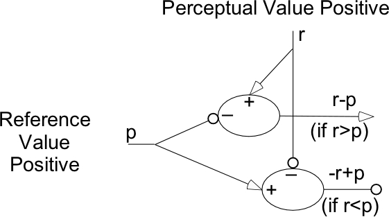
Back to my Figure 4.6, about which I agreed last night with Erling
that only the top-left quadrant was needed (reproduced here).

All the values of the signals in the diagram are necessarily
non-negative. But what if p represents a negative value from a
relationship perception, while r represents a positive reference
value for that perception? This circuit would produce an output from
one or other unit according to the difference of absolute values of
reference and perception, not according to the difference between
the true reference and true perceptual values. If both p and r
represent negative “true” values, the non-zero output would come
from the wrong unit.
The other quadrants of Figure 4.6 seem to be needed, where "-p" and
“-r” are the signal paths carrying the absolute values corresponding
to a negative perceptual or reference value. For example, in Fred’s
intuition about the car-in-lane perception, the “left of centre”
output might be on the “-p” path, whereas “right of centre” output
would be represented by “p”. We need separate signal paths for both,
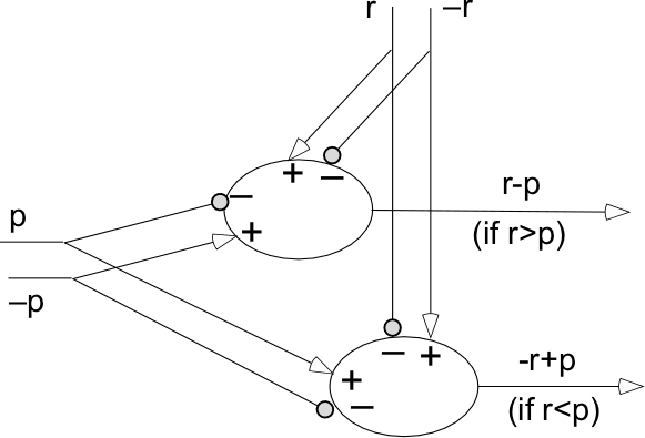
if appropriate to the perception concerned, as in this figure:

This Figure is the four quadrants of my original Figure 4.6
compressed into one. Only one of p and -p, or of r and -r, can be
non-zero at any one time. If the “true” r is positive and the “true”
p is negative, their absolute values will add together to provide a
“true” r-p output from the upper unit, since any positive r (true)
is necessarily greater than any negative p (true). If those signs
are reversed, the lower unit will provide the appropriate value as a
positive output, the fact that the sign is reversed being signalled
only by the fact that this line has a positive value and the other
does not. If both true r and true p are of the same sign, then the
appropriate output line has a positive non-zero value while the
other output is zero.
In a real neuron, the four inputs shown in the figure represent
hundreds or thousands of synaptic connections, which offer millions
of different possibilities. Just as we do when representing by a
“neural current” lots of firings by different nerves, recognizing
the approximation, so, too can we examine the effects of similar
approximations to allow many potentially different effects, one of
which might be the effective arithmetic summation of excitation and
inhibition.
Anyway, the above is this morning's attempt at clarifying Figure
4.6, recognizing that all four inputs to the two half-comparator
units are needed only in cases where the true perceptual value (and
hence the reference value) can be of either sign, as would be the
case when the perception is of a relationship.
Maybe new comments will show me that I need to rethink, but my
rethinking after Erling’s critique seems to have led me around the
circle back to what I was presumably thinking when I drew the first
Figure 4.6. I don’t know if it is correct, but that’s the way it
seems this morning.
Martin
···
[Martin Taylor 2017.08.25.20.36]
[From Erling Jorgensen (2017.08.24 1655 EDT)]
Martin Taylor 2017.08.24.16.45
Erling Jorgensen (2017.08.24 1630 EDT)
>>EJ: You make the comment in the explanation ofthe figure, that “Incoming negative values are the result
of inhibition or some other inversion not shown in the
Figure.” I don’t know how there can be negative values
conveyed apart from inhibitory connections.
MT: Exactly. That was what I tried to explain.
>>EJ: The issue is this. You have supposednegative values on the axon then coming and making an
excitatory connection, but I don’t think that can happen,
because a negative value is constituted by that inhibitory
connection at the synapse. So wherever you have -r or -p,
I think that is a fiction.
MT: It certainly would be!
EJ: Good. I'm glad we are in agreement on thesepoints. From my perspective, all that is needed is the
upper left quadrant of your Figure 4.6. That covers the
way to get bi-directional comparators. All incoming
values are positive. For one comparator, invert the sign
of the perception on the way in, through an inhibitory
connection (and several options are available to
accomplish that.) For the other comparator, invert the
sign of the reference on the way in, also via an
inhibitory connection (using one of those aforementioned
options.) That covers it.
    Yes.


    Looking back at the Figure, I know what I intended to get
across, which was the four different effects of combinations of
positive and negative implied values of reference and perception
on the circuit at the top left, which was intended as the only
circuit. But it’s a very confusing figure. since I used points
and circles as arrowheads, which I know often signify excitation
versus inhibition. And I used + and - symbols within the two
comparators for apparently the same purpose. But now even I
don’t know what I meant in each case.Ignoring the figure, which I will redraw (I hope) lessconfusingly, I am quite sure we agree on what would be required.
You describe exactly what I had imagined I was depicting. All
four quadrants referred to that same circuit, in ways that
seemed obvious when I drew it but now do not.So thanks for the critique. It's good not to have such aconfusing figure in the book. I hope the next iteration will be
intelligible even to me a couple of years hence.Martin