[Martin Taylor 2010.01.23.14.39]
[From Bill Powers (2010.01.20.0800 MST)]
Martin Taylor 2010.01.20.09.37 –
In a private
conversation, I
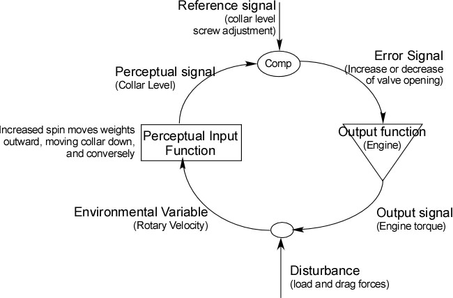
introduced the Watt Governor as an example of a perceptual control
system
whose paths and variables are exposed. My correspondent said that my
PCT
diagram was an incorrect representation of the governor, and I would
like
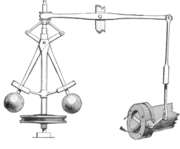
the opinions of PCT old hands as to what is wrong with it. The small
picture is from Wikipedia, and I take the speed adjustment to be done
by
screwing up or down the collar that is connected to the lever
arm.
That’s what I would assume, too, and if so, your diagram is correct
PCT-wise.
Thanks for that. It’s reassuring, because while I was away I found
myself mulling over it, and I couldn’t find any obvious mistakes (other
than possibly calling the error signal the valve opening, rather than
the lever angle that causes the changes in the valve opening). There’s
no need for a valve to exist. All that is needed is for the engine
torque to be adjustable by something moved by the lever arm, so it
could be an electric motor, a waterwheel, or whatever.
The reference level for speed can be changed by anything
that
can alter the valve opening while the flyball itself is running at a
constant speed, so there might be aspects of the mechanism that aren’t
visible in the diagram. There is what looks like a length adjustment
(like the collar on a turnbuckle with opposite threadings at the two
ends) on the rod just above the valve itself – that would also change
the reference level, and might be used to adjust the calibration of the
other speed adjustment.
If you mean an adjustment of the length of one lever arm, wouldn’t that
change the gain rather than the reference? The comparator, it seems to
me, is comparing the height of the collar against the reference height
of the collar. The reference level is a reference for the perceptual
variable, not the corresponding environmental variable, which is the
speed.
Is adjusting the speed the the basis of your friend’s objection? How
does
he (or it) think it works?
I don’t know what the objection might be. Here’s the complete message:
···
=============
I’ve just
had a quick look at my
engineering notes on governors and feedback.
Your control
system schematic of the
governor is incorrect.
=============
I asked for clarification, either in the form of explaining my error or
of a correct diagram, but so far, none has been forthcoming.
I had thought the Watt Governor was a very good illustration of the
components of a PCT control loop, since every function (except the
internals of the engine) and the form of every signal is explicitly
visible. It shows how a feedback loop can operate with the signals
being of very different kinds in different parts of the loop, and yet
remain coherent. Usually we talk in the abstract, or assume that the
signals, other than those in the environmental feedback loop, are rates
of neural firing. But here we have a loop in which the important
environmental variable is rotary velocity, the perceptual signal is the
height of the collar, the reference value is changed by adjusting a
screw, the error signal is a lever arm angle, and the output is a
torque applied to a load and losses, all plain to see.
My correspondent has been under the impression that the reference
signal must supply the energy that powers the signal paths in the loop.
I’ve been trying different ways to disabuse him of that notion, and I
thought that using the Watt Governor, in which the reference value is
adjusted by turning a screw, would provide an irrefutable
counter-example. Apparently the effort failed, because my schematic is
said to be incorrect. No doubt I will discover in what way it is
incorrect, but in the interim, I’m glad to have your opinion that it is
believably correct.
Martin