The Baltieri, Buckley & Bruineberg paper (henceforth BB&B) was tough going, especially the FEP part, but I think I got the gist of their two models of the Watt flyball (centrifugal) governor. I’ll call the first model the “standard” model and the second the FEP model. I’ll try to compare both models to a PCT model although BB&B compared only the FEP model to PCT.
First a little about the flyball governor, shown here:
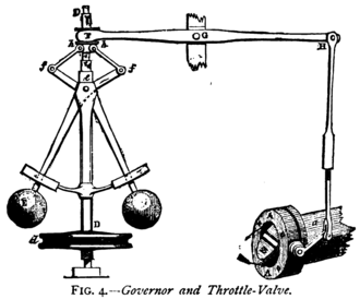
This device was (and still is, I suppose) used on steam engines to control the speed of the engine, w, keeping it constant despite variations in load, G. A shaft (the vertical rod in the diagram) connects the governor to the engine (not shown) and rotates at a speed proportional to w. The two flyballs at the end of arms rotate along with rotation of the shaft, causing a centrifugal force that lifts the arms in proportion to w. Thus, the arms attached to the flyballs form an angle, psi, with respect to vertical that increases with increases in w.
Because of the way the arms are attached to the small levers above them, an increase in psi pulls the left end of the horizontal bar (top of the diagram) down, thus lifting the lever that closes the throttle valve. The size of the throttle value opening, tv, affects the speed of the engine, w; w is positively relative to engine speed and, therefore negatively related to psi.
Standard Analysis of the Flyball Governor
BB&B’s standard analysis takes advantage of the relationships described above to give a mathematical description of the physics of the flyball governor. Here’s a simplified PCT version of their mathematical analysis. The analysis requires two sets of equations, one that defines the behavior of the System (the governor) and the other that defines the system’s Environment.
In this analysis, italicized variables correspond to those used in BB&B; non-italicized variables are added for clarity of correspondence to PCT.
System
- psi = p(w)
- tv = f(r - psi)
Equation 1 says that flyball arm angle, psi, is a function of engine speed, w. I call the function p() because in the BB&B analysis, psi corresponds to the PCT perceptual variable. Equation 2 says that the throttle valve opening, tv, is a function of the difference between psi and the reference, r, for psi, which is essentially the reference for the speed of the engine. When engine speed decreases, psi goes below the reference, r - psi goes positive and the throttle valve opening, tv, increases, which increases engine speed; when engine speed increases, psi goes above the reference, r - psi goes negative and the throttle valve opening decreases, which increases the engine speed.
Environment
- w = g (tv, G)
Equation 3 is the function relating the effect of system output, tv, and external disturbances, G (which BB&B define as “torque induced by engine load”) on engine speed.
The controlled variable in this system is engine speed, w. A dynamic analysis of the system defined by equations 1-3 gives what BB&B call the equilibrium state of the system and what PCT calls the reference state of w. In both cases this state of w is proportional to the system’s reference specification for the state of the perception of w. In PCT, this reference specification is r so the reference state of w is proportional to r: w ~ k*r.
I knew that the same must be true in the BB&B “standard analysis” but it took me a while to figure out that it is g, gravitational acceleration, that functions as the reference specification in that analysis. The proportional relationship between w and g – the equivalent of the proportional relationship between w and r in the PCT analysis – can be found by solving equation 4 of BB&B for w (you’ll find that w is proportional to the square root of g).
My discovery that g in the BB&B analysis is equivalent to r in the PCT analysis made it clear that the difference between the two analyses is simply one of perspective. The BB&B analysis is done from the engineering perspective – the perspective of the user of the flyball governor – while the PCT analysis is done (or should be done) from the system perspective – the perspective of the governor itself. This difference led to my making a mistake in my PCT analysis and catching one in the BB&B analysis. The mistake is taking psi – the angle of the flyball arm relative to vertical – as the controlled perceptual variable.
In a control system the perceptual and reference variable must be of the same type. You can’t compare apples and oranges and the basis of control is continuous comparison of perception and reference values. Being a control engineer, Powers understood this when he applied control theory to the behavior of living systems. In PCT, both perceptual and reference variables are assumed to be neural currents. They are not only the same type of variables but we understand the physiology that allows these variables to be compared to each other by subtraction (because there are excitatory and inhibitory connections between neurons).
If g is the reference specification in a flyball governor then the perception to which it is compared must be of the same type – a force. And, sure enough, it is. The actual perception that is controlled by the flyball governor is the centrifugal force, Fc, produced by the spinning flyballs. Like psi, the angle of the arms attached to the flyballs, Fc is proportional to w, the speed of the motor. When the motor is running at a speed such that Fc = g, then Fc - g = 0 and there is no need to change the throttle opening, tv; the motor is running at the reference speed. When Fc is greater than g then the motor is going too fast and the flyball arms will pull the horizontal lever down causing the throttle valve to close. When Fc is less than g then the motor is going too slow and the flyball arms will will pull the horizontal lever up causing the throttle valve to open. The angle of the flyball arms, psi, can now be seen as analogous to the error signal in PCT since it is connected to the lever that varies the throttle opening (system output).
Mistaking psi for the actual controlled perception is not a particularly big deal when working from the engineering perspective unless one is interested in designing a governor with a variable reference. Since the force of gravity is a constant, producing a variable reference requires the ability to vary the restoring force acting against Fc. This can be done by inserting a spring of variable stiffness at the appropriate point on the shaft of the governor.
FEP Analysis of the Flyball Governor
The FEP model is explicitly done from the system’s perspective. Indeed, citing Powers (1973), they say that they take the “…rather unusual reading of the engine-governor coupled system: an agent trying to stabilize its observations, i.e., the perceived angle of the flyball arms”. This perspective seems to have allowed them to avoid making the mistake of having the controlled perception and the reference for the state of that perception be of different types. In this case it seems that both are the same type: both are angles. The perception is the observed angle, psi, and the reference is the predicted angle, x. The “error” in this system is apparently the free energy, F, which is proportional to the conditional probability of psi given x (equation 7 in BB&B). The system continuously takes action, a, based on F, presumably as the means of keeping F close to 1.0.
The FEP model of the flyball governor includes functions that the governor cannot and does not carry out. Most obviously, it can’t and doesn’t compute the conditional probability of psi given x. The authors of the model acknowledge this by saying that their FEP model is an “as if” model; the governor behaves as if it is acting to maintain a high conditional probability of psi given x. So one wonders why BB&B wanted to show that you could model the behavior a flyball governor using the FEP model. It can’t be because they wanted to show what you could learn about the governor from the model. The FEP model explains nothing about how the governor actually works and, indeed, is very misleading.
I think the same applies to the application of FEP to the controlling done by living systems. How, for example, does the nervous system come up with the “true value” (x in the example) of the variable being controlled? How does it represent that variable in order to compare it to the observed value of the variable psi in the example)? How does it compute and then store the probabilities necessary to determine the conditional probability the observation given the true (or predicted?) state of the world? For example, in order to compute P(psi| x) per Bayes’ theorem the system would have to know P(x| psi), P(psi) and P(x) for every x that is to be controlled. The idea that organisms do this in order to control the variables they need to control seems highly implausible and, per PCT, completely unnecessary.
I think the BB&B paper shows very clearly that the FEP model is just an “as if” model of the controlling done by living systems, and a very misleading one at that. Even though FEP is popular and trendy, I think the best course for those who want to actually understand the behavior of living systems is to ignore the “as if” theory that is FEP and stick with the “like this” theory, which is PCT.