[Martin Taylor 2014.04.26.09.33]
[Rupert Young (2014.04.26 16.00)]
That's pretty much what I was thinking though you've put it
clearly and filled in a few blanks of which I was unsure.
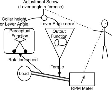
It is supposed to be controlling speed yet there is no speed
sensor in either picture, though perhaps it is taken for granted
in “B”, as Rick says. But for the governor itself there is no
such sensor. The component that is sensing (perceiving) the
speed is the human, perhaps via a meter of some sort. So “B” is
missing the fundamental part of the system that makes it a speed
controller. The governor itself does not control speed, but some
physical arrangement; the collar height.
However, I am wondering if the governor on its own is a
self-regulating system rather than a control system (all control
systems are self-regulating but not all self-regulating systems
are control systems), in that an equilibrium is maintained due
to the physical configuration and interaction of the components.
I'm getting quite uncertain as to what is meant by a
“self-regulating system”. So I can’t answer you directly. But if I
substitute “negative feedback loop”, I quite agree. Not all negative
feedback loops are control systems. However, even in control loops,
“equilibrium is maintained due to the physical configuration and
interaction of the components.”
What distinguishes the class of control systems from other negative
feedback loops is the distribution of energy gain. The perceiving
side of a control loop is, ideally, a zero-energy area. Of course it
does take some energy, either provided by the environment (photons,
for example) or internally (chemistry that drives nerve impulses).
The output side, on the other hand, uses an external energy source
to deliver sufficient energy to the environment to enable the
control loop to counter the energy of disturbances. You don’t
necessarily see the use of this external energy supply at any
particular point in a complex circuit, except that in a control
system it must occur between the computation of the error value and
the point where the disturbance acts.
In the case of the flyball governor, the only external energy source
is the fuel to the steam engine. The disturbance is a variable load
that would, in the absence of the engine, set the rotational speed
– possibly at zero, but maybe not, if the load has its own rotary
drive. Thinking of the circuit flow, any energy that drives the
flyball comes from what is left AFTER the disturbance, and it takes
only a small amount of energy to change the rotational speed of the
flyball. In fact, the flyball need not consist of massive weights.
It could be microscopic (or even nanoscopic) provided that its
effect is eventually to change the steam valve opening, an action
that also takes very little energy compared to the energy output of
the steam engine.
The disparity between the energy requirements of the flyball side of
the circuit and the steam-engine side is what makes this circuit a
control system as opposed to a generic negative feedback loop.
If I understand you correctly adding weight (disturbance) to
the flyballs would affect the system so that the equilibrium
would find a different value.
That's correct.
In other words there is no variable maintained at a
reference.
Yes there is. On the flyball side, you could call it the swing
radius of the flyballs or the collar level or the lever arm angle,
all of which change together as the rotary shaft speed changes. If
the steam engine power changes or the load changes, these variables
all change so as to bring the rotary speed back (nearly) to the
reference value.
This might be something like predator-prey ratio regulation
and adding a new species would upset the equilibrium, but a
new equilibrium would arise.
Something like, yes, in the sense that the predator-prey system is a
negative feedback loop, and if the flyball and steam valve
relationships to the values they influence were sufficiently
nonlinear, I suppose the flyball system might oscillate or even hunt
chaotically rather than stabilize at some rotary speed (I haven’t
checked this possibility, so it might not occur). And I suppose
there is an asymmetry in the predator-prey relation, in that the
predator gets its energy from the prey whereas the prey gets its
from parts of its external environment that don’t include the
predator. But again, I haven’t followed this through to see how real
the analogy might be. Personally, I find the analogy more misleading
than helpful.
So, then, the only thing that is a control system within the
steam engine speed system is the human?
No, that doesn't follow. The lever arm angle is controlled, and the
reference value for that control is set by the human.
I think one of the problems with conceiving this system is a problem
generic to all two-level systems that have only one control unit at
each level. The problem is that there is only one environmental and
perceptual variable at the lower level, and therefore the perceptual
variable at the upper level is a function of the same environmental
variable. Functionally, if the perceptual variable at level 1 is
P1(input) (collar height = P(rotary speed)), then the perceptual
variable at level 2 is P2(P1(input)) , which can be written as a
single function P12(input), which means that from outside it looks
as though level 2 is controlling a direct perception of the input
(although in the flyball case, we think the human perceives the
rotary speed through a different channel). It is, but the mechanism
of that control is by providing a reference value to the lower
level, not by acting in the environment. Hence, any experiment with
a single environmental variable that the subject can influence will
give results that will not be easy to use for discriminating between
single-level and multi-level control structures.
Martin
···
(Martin Taylor
2014.04.22.09.35)
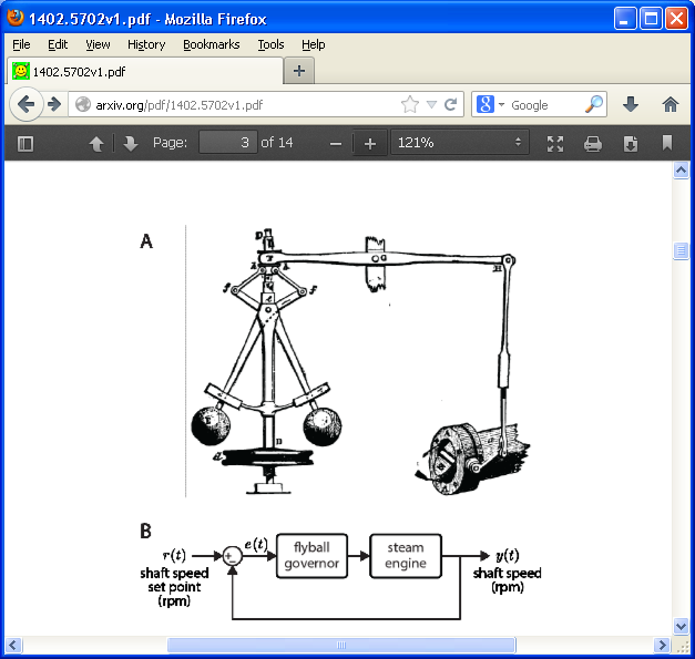
Let's start with the shaft
rotational velocity, since that’s what is supposed to be
controlled to match some reference velocity. Where is the
reference velocity set? Nothing in the “A” picture shows a
reference rpm input, which is clearly shown in the “B”
diagram. So there’s a mismatch between the halves of the
figure right off the bat.
So far, so good. But what
actually is being controlled here? It’s hard to tell,
because all the variables are being stabilized around the
loop, and there is no reference value setting for any of
them – or is there? It’s hard to tell from the A picture,
but it looks as though there are two adjustments. One is at
the collar that connects the left end of the lever to the
top of the flyball mechanism, and the other is the screw
adjustment on the vertical link rod. The first changes the
offset relation between flyball speed and lever angle. The
second affects the offset relation between lever angle and
valve opening. These are human-operated adjustments, which
would be the outputs of some human control system,
presumably one that controls a perception of shaft
rotational velocity.